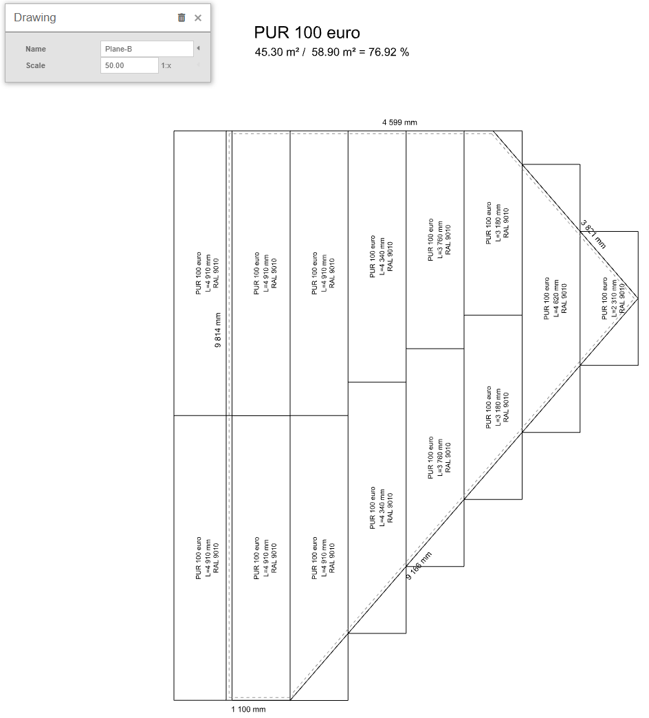
📏 Creating a cladding drawing for the roof plane
The roof plane layout drawing is a key part of the building design process, allowing you to translate the design plans into a practical design on the roof. This drawing serves as a detailed guide for builders when installing a roof system and contains important information on material placement, joints and all technical aspects that are essential for a quality and safe roof construction.
In HiStruct, complete drawings for all roof planes are automatically generated based on the 3D model. To edit these drawings, simply navigate to a specific roof plane and click on the Drawings button.
At the same time, these drawings are always generated automatically within the outputs, for example in the roofing BOM.
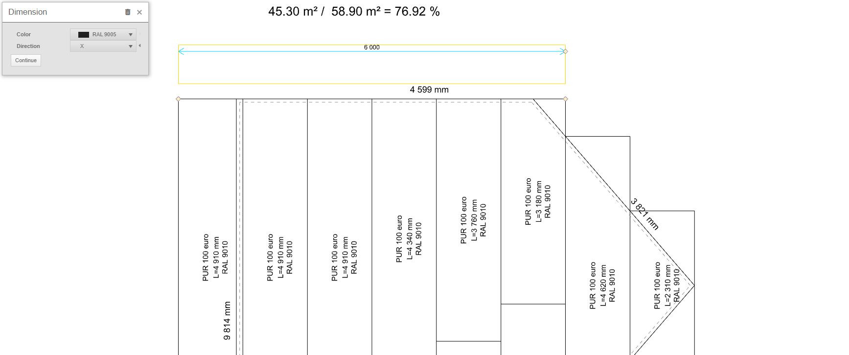
Adding dimensions
You can enter a datum by clicking on the Dot button, selecting the two points for which you want to plot a datum, and then specifying the distance of the plotting line. After clicking on the dimension, it is possible not only to change its color, but also to specify the direction in which the dimension will be plotted. The direction can be set to X, Y, or Default, which will measure the shortest distance between these points. Alternatively, the Angle direction can be selected, which will plot the dimension at the selected angle. The last option in the dimension edit is the Continue button, which will generate another dimension in the same direction.
If I want to edit any point of my added dimension, I just click on the dimension and by moving the yellow points I am already editing the dimension.
Adding a line
Another element that can be added to a drawing is polyline. For this line, only the color can be changed.